|
The IPX systems support flexible voice network topologies. Many factors could impact on the voice intranet network topology design:
Number of IPX systems;
Type of IPX models;
Availability of public IP address for IPX systems;
Involvements of firewall/NAT at each location;
The topology of voice intranet could be a mesh network, star network, or a mix of both. At different location, an IPX could be in different roles. For example, it could be a peer of a neighbor, a server of some clients, and a client of a server.
2 IPX Network
This is the simplest case, peer to peer.
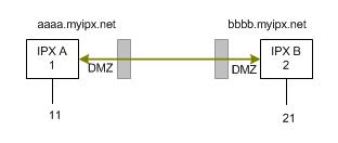
On each site, configure the ADSL router with DMZ or port forwarding for IPX. In each IPX configuration, the other end becomes its peer. The configuration page is "advanced voice>voice intranet>peer list". Do not forget to set IPX itself's domain name as its voip signaling address in page: "advanced voice>voice intranet>intranet option".
Mesh Network
For 10 or less number of IPX systems, a mesh network is feasible. If NAT/firewall is in the front of an IPX system, DMZ or port forwarding is needed.
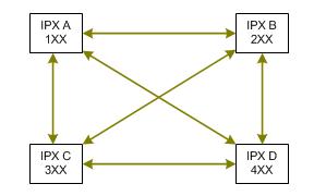
In the diagram, each IPX needs to configure with 3 peers.
Start Network
When the number of IPX systems in a voice intranet is more than 10, adding a new IPX to the system could involve some work on each node. Maintenance of such the mesh network becomes difficult when the mesh network is big. Star network helps to solve this problem.
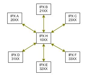
n the diagram, the IPX A in server role should have a public IP address (dynamic IP address is fine). Other IPX can be behind NAT/firewall, where no DMZ or port forwarding configuration would be needed.
Adding a new IPX to the network becomes simpler. But the server is playing an important role. Its reliability and performance are critical.
Mix of Mesh and Star Network
Between main offices can be a mesh network. In each location, it can be a star network, where the IPX in a main office is the local server. The IPX in the main offices should have public IP addresses.
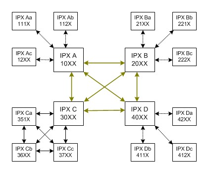
In the diagram, the solid lines represent peer to peer relationship; the dashed lines represent server client relationship.
Example IPX A:
The IPX A has peer list:
For destination 2, go to peer B (2 is a faked IPX code for B region);
For destination 3, go to peer C (3 is a faked IPX code for C region);
For destination 4; go to peer D (4 is a faked IPX code for D region);
The IPX A also has a client list:
Client IPX Aa, IPX code 111;
Client IPX Ab, IPX code 112;
Client IPX Ac, IPX code 12.
Example IPX Bb:
The IPX Bb has a server: IPX B is the server of IPX Bb.
Example IPX Ca:
The IPX Ca has peer list:
For faked IPX code: 30,1,2,4, peer is IPX C;
For IPX code 36, peer is IPX Cb;
For IPX code 37, peer is IPX Cc;
In the last example, IPX C is viewed as the proxy for IPX Ca, Cb and Cc.
Back
|
|
|